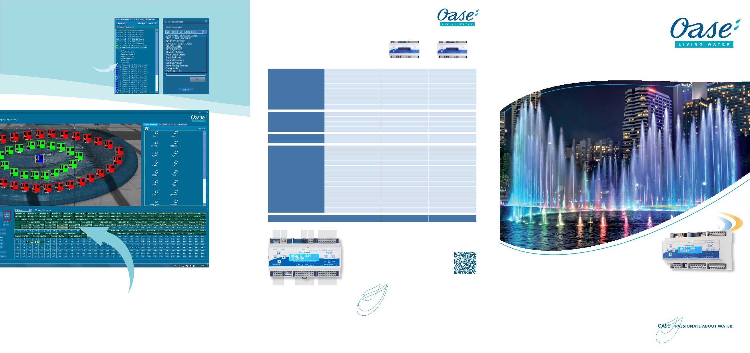
The DMX patchgrid gives an overview of channel allocation and the DMX channel value output. The cable con-
figuration of shows can be controlled and modified via Drag&Drop.
DMX patchgrid
The WECS II hardware is able to exchange data
with the WEPS-RDM-monitor. So it can write, for
example, DMX addresses in the devices or read out
sensor data and other device-specific parameters.
RDM (Remote Device Management) capable devi-
ces are listed. These can be linked to the particular
„Assemblies“ with Drag&Drop.
RDM monitoring
WECS II 512
WECS II 1024
Water Entertainment
Control System
D
M
X
/
R
D
M
OASE GmbH
· Postfach 20 69 · 48469 Hörstel
Telefon: +49 5454 80-0 · Fax: +49 5454 80-9253 ·
·
32628/05G
SF
The products shown/offered are designed exclusively for the described purpose. If the products we have cited are used inappropriately, we assume no liability whatsoever for defects or damage that occurs due to this circumstance.
Text and image descriptions do not constitute any assurances of characteristics. Minor deviations in our products do not constitute a defect. Use of our image data is only permitted after obtaining prior written approval from OASE.
Hardware
512 channel RDM/DMX output
∞
∞
1024 channel RDM/DMX output
∞
Easy to use front panel setup
∞
∞
Interface 1024 channel
∞
∞
8 digital output
∞
∞
8 digital input
∞
∞
DIN rail housing
∞
∞
Audio output
∞
Stand alone
Stand alone capable
∞
∞
Stand alone micro SD card 4GB
∞
∞
Show upload via micro SD card
∞
∞
Stand alone calendar
∞
∞
Connectivity
Ethernet RJ45 10/100 Mbit
∞
∞
Order no.
56491
56492
Software
Fixture library
∞
∞
Pachting
∞
∞
Operating & monitoring (Live page)
∞
∞
RDMmonitoring
∞
∞
Logbook files
∞
∞
Scene
∞
∞
Sequences
∞
∞
Scheduler
∞
∞
DMX channel preview
∞
∞
Effects: SIN, COS, RECT, SAW UP/-DOWN
∞
∞
Matrix programming
∞
∞
Time schedule with internal clock
∞
∞
Media support audio
∞
WECS II 512/DMX/02 WECS II 1024/DMX/02
WECS II overview
A
Any number of shows or sequences for a project can be saved
on the micro SD card (4GB included).
B
RJ-45 Ethernet
C
Audio 3,5 mm stereo jack, galvanically isolated
D
Connection of vollage supply +24V DC for digital outputs (-/+)
E
8x digital output 1A/output, galvanically isolated
F
4x connection to power supply (++/--) 15-24 V DC /8W
G
2x DMX-RDM outputs, galvanically isolated
H
2x grounding for digital inputs
I
8x digital inputs, galvanically isolated
A B
C D
E
I
H G
F


